FPGA setup and hold timing budget
Calculate setup and hold slack for a single-cycle, same-frequency register-to-register path. Enter maximum delays for setup, minimum delays for hold, and signed clock skew.
Calculator
Sign convention and equations
Skew S is the capture-clock arrival time minus the launch-clock arrival time. A later capture clock gives positive S, which helps the single-cycle setup check and tightens the same-edge hold check.
Setup slack = T + S − tCQ,max − tDATA,max − tSETUP − Usetup
Hold slack  = tCQ,min + tDATA,min − S − tHOLD − Uhold
Minimum period from setup = tCQ,max + tDATA,max + tSETUP + Usetup − S
All inputs are in nanoseconds. Data path delay includes combinational-cell and routing delay after the launch register’s Q pin. Uncertainties are entered as nonnegative margins. Setup and hold cell requirements may be signed.
Worked example
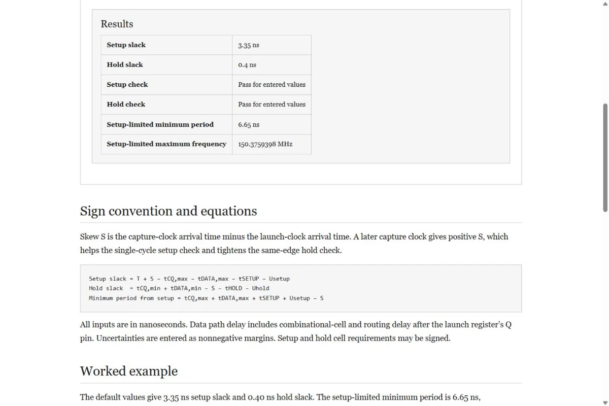
The default values give 3.35 ns setup slack and 0.40 ns hold slack. The setup-limited minimum period is 6.65 ns, corresponding to approximately 150.376 MHz if all entered path delays and margins remain valid.
Model limits
This worksheet assumes rising-edge launch and capture, one cycle for setup, and the same edge for hold. It omits clock reconvergence pessimism removal, on-chip variation, inter-clock edge selection, multicycle exceptions, generated clocks, and recovery/removal checks. A negative hold slack requires a hold fix regardless of the setup-limited frequency.
Use separate min/max timing corners from the device reports. The calculated maximum frequency describes this path and these inputs, rather than the complete FPGA implementation.
Related tools
- FPGA clock-enable divider — Choose the enable rate for logic that remains in one clock domain.
- SystemVerilog clock generator — Generate clock stimulus at a chosen simulation frequency.